
Plate Heat Exchanger Fouling: Prevention and Cleaning Strategies
- Gerry Wagner

- 2 days ago
- 8 min read
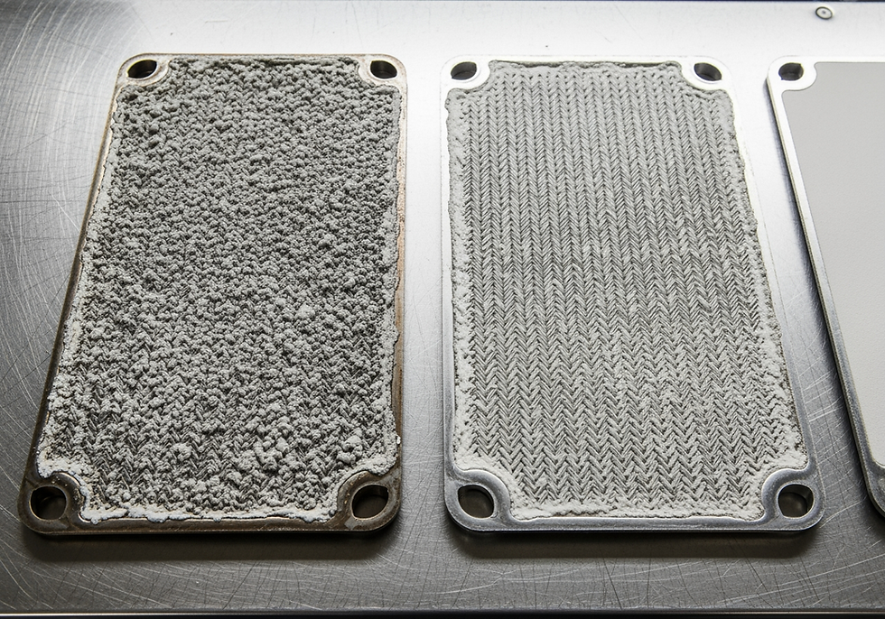
Plate heat exchanger fouling reduces thermal performance by up to 50% within months in poorly managed systems. Deposits accumulate on heat transfer surfaces, increasing pressure drop and reducing thermal efficiency progressively. Left unaddressed, fouling leads to unplanned shutdowns, elevated energy costs, and premature equipment failure.
Industrial facilities across mining, manufacturing, and processing sectors face ongoing fouling prevention heat exchanger challenges. Cooling water systems develop scale deposits. Process fluids leave organic residues. Biological growth blocks narrow plate channels. Understanding fouling mechanisms and implementing targeted prevention strategies protects equipment investment and maintains system performance throughout equipment service life.
Understanding Plate Heat Exchanger Fouling Mechanisms
The Five Primary Fouling Types
Plate heat exchanger fouling occurs through five primary mechanisms, each requiring different prevention and cleaning approaches.
Crystallisation fouling develops when dissolved minerals precipitate onto heat transfer surfaces as fluid temperature changes. Calcium carbonate, calcium sulphate, and silica form hard scale deposits that resist mechanical removal and require acid-based chemical cleaning. This mechanism dominates in cooling water applications using bore water or recycled process water with high hardness levels.
Particulate fouling results from suspended solids accumulating in plate channels. Rust particles, sand, and process contaminants settle in low-velocity zones. Fine particles penetrate deep into corrugated plate patterns, reducing flow area and increasing pressure drop. Mining operations and dusty processing environments experience accelerated particulate fouling rates.
Plate heat exchangers designed for fouling-prone services are available with wide-gap plate configurations (5-7mm) that reduce particulate accumulation and extend cleaning intervals compared to standard narrow-gap designs.
Chemical Reaction, Corrosion, and Biological Fouling
Chemical reaction fouling produces deposits through polymerisation or chemical transformation at elevated temperatures. Organic compounds break down and form carbonaceous layers. Lubricating oils oxidise into varnish-like films that bond strongly to stainless steel surfaces, requiring aggressive cleaning chemistry.
Corrosion fouling generates metal oxides that deposit on heat transfer surfaces. Chloride attack on stainless steel creates pitting corrosion products. Iron oxide particles from carbon steel system components contribute to fouling while accelerating further corrosion. Corrosion fouling indicates system chemistry problems requiring immediate attention beyond simple cleaning.
Biological fouling biofilm heat exchanger growth occurs when microorganisms colonise heat transfer surfaces. Bacteria, algae, and fungi form biofilms that trap particulates and reduce heat transfer. Biological fouling biofilm heat exchanger development accelerates rapidly in warm, nutrient-rich cooling water systems. Cooling towers and evaporative systems provide ideal conditions for biological proliferation if treatment is inadequate.
How Fouling Affects System Performance
Thermal Resistance and Heat Transfer Degradation
Plate heat exchanger fouling impacts performance through several degradation mechanisms. Thermal resistance increases as deposits insulate heat transfer surfaces. A 1mm scale layer reduces the heat transfer coefficient by 30-40%. Process outlet temperatures drift from setpoints. Energy consumption rises as systems work harder to reach target temperatures.
Regular fouling monitoring performance degradation tracking against commissioning baseline data provides the earliest opportunity to intervene. Tracking the heat transfer coefficient against commissioning baseline data quantifies actual degradation accurately.
Cooling systems analysis provides systematic performance assessment against design specifications. Calculating heat transfer coefficients from measured temperatures and flow rates quantifies fouling impact on thermal performance precisely.
Pressure Drop and Flow Distribution
Pressure drop escalates when deposits narrow flow channels. Plate heat exchangers use 3-5mm gaps for efficient heat transfer. Even thin fouling layers significantly restrict flow. Pressure drop can double or triple in severe cases, increasing pumping energy costs and stressing gaskets and plates.
Fouling monitoring performance degradation through pressure drop tracking provides the earliest reliable indicator. A 20-30% increase in differential pressure across the unit at constant flow rate indicates significant fouling accumulation requiring attention.
Flow distribution also deteriorates as some channels block while others remain relatively clear. Uneven fouling distribution creates preferential flow paths, reducing effective heat transfer area. Dead zones develop where stagnant fluid accelerates further fouling, compounding the performance problem.
Fouling Prevention Through System Design
Fluid Velocity and Plate Pattern Selection
Effective fouling prevention heat exchanger design begins with fluid velocity selection. High velocity above 0.8 m/s prevents particle settling and disrupts deposit formation on plate surfaces. Plate heat exchangers achieve these velocities in compact designs. However, excessive velocity increases pressure drop and erosion risk.
Temperature control prevents crystallisation fouling cooling water by keeping bulk fluid temperature below the scaling threshold. Calcium carbonate precipitates rapidly above 60°C in hard water. Correct heat exchanger sizing maintains outlet temperatures below critical scaling limits under all operating conditions.
Plate pattern selection influences fouling susceptibility directly. Wide-gap plates handle particulate-laden fluids better than narrow-gap designs. Hard corrugation patterns create higher turbulence, reducing deposition rates at the cost of slightly higher pressure drop. Plate pattern should be selected based on fluid characteristics and fouling potential, not thermal efficiency alone.
Strainer Installation and Material Selection
Strainer installation removes particulates before they enter plate channels. Installing 1-2mm mesh strainers on both hot and cold sides prevents the majority of particulate fouling. Automatic backwash strainers provide continuous protection without manual intervention.
Material selection affects corrosion fouling rates. Standard 316 stainless steel suits most applications. Chloride-rich environments require 904L stainless or titanium plates. Correct material specification eliminates corrosion fouling at its source.
Industrial cooling towers that supply cooling water to plate heat exchangers benefit from integrated cooling tower water treatment scale inhibitor programmes. These programmes address biological fouling biofilm heat exchanger growth in the tower basin before contaminated water reaches the heat exchanger.
Water Treatment for Fouling Control
Chemical Treatment and pH Control
Effective water treatment scale inhibitor programmes prevent scale formation and biological growth in cooling systems. Phosphonate-based inhibitors prevent calcium carbonate and calcium sulphate precipitation. Polymer dispersants keep particles suspended rather than depositing on surfaces. Biocides control bacterial and algal growth.
pH control influences both crystallisation fouling cooling water tendency and corrosion rates simultaneously. Maintaining pH between 7.5 and 8.5 balances scale prevention against corrosion control for most cooling water systems. Continuous pH monitoring with automated dosing maintains stable chemistry across variable operating conditions.
Allied Heat Transfer provides fouling prevention heat exchanger guidance and performance monitoring support for industrial cooling systems across Australia, with engineering expertise across mining, manufacturing, and processing sectors.
Hardness Management and Filtration
Hardness management reduces scaling potential in crystallisation fouling cooling water applications. Ion exchange water softening removes calcium and magnesium ions before they form scale. Conductivity monitoring indicates dissolved solids concentration from evaporative concentration. Blowdown removes concentrated solids, maintaining acceptable cooling water chemistry.
Side-stream filtration removes suspended solids causing particulate fouling. Treating 5-10% of system flow through media filters captures particles down to 5-10 microns. Automatic backwash cycles maintain continuous filter performance.
Monitoring and Early Detection
Pressure Drop and Temperature Tracking
Regular fouling monitoring performance degradation identification catches fouling accumulation before performance loss becomes severe or equipment damage results.
Differential pressure gauges installed across heat exchangers record baseline clean performance. A 20% increase from baseline at consistent flow rates indicates significant fouling requiring scheduled cleaning. Pressure drop trend plots identify accelerating fouling rates requiring more frequent cleaning or system chemistry adjustment.
Temperature monitoring reveals heat transfer degradation independent of pressure drop changes. Track approach temperature - the difference between outlet temperature and theoretical maximum for the given inlet conditions. Increasing approach temperature indicates plate heat exchanger fouling even when pressure drop change is modest.
Thermal Performance Calculations
Thermal performance testing quantifies fouling impact precisely. Calculating the overall heat transfer coefficient from measured temperatures and flow rates, then comparing against clean condition baseline, identifies degradation accurately. A 30% reduction in heat transfer coefficient from baseline justifies cleaning even if pressure drop indicators are borderline.
Heat exchanger cleaning Australia-wide maintenance programmes benefit from this combination of pressure drop and thermal performance monitoring. The two-metric approach catches fouling that either indicator alone might miss.
Chemical Cleaning Methods
Acid Cleaning for Mineral Scale
Chemical cleaning removes deposits without disassembling heat exchangers, making it the preferred first approach for most fouling conditions.
Acid cleaning dissolves mineral scale deposits effectively. Hydrochloric acid (5-10% solution) removes calcium carbonate rapidly. Nitric acid (5-10%) cleans stainless steel surfaces without elevated corrosion risk. Phosphoric acid provides milder cleaning for light scale accumulation. Solutions circulate at 40-60°C for 2-4 hours with corrosion inhibitors protecting base metal throughout the cycle.
Chemical cleaning services for plate heat exchanger fouling caused by mineral scale restore performance without disassembly. Complete rinsing and pH verification confirm clean condition before return to service.
Alkaline and Detergent Cleaning
Alkaline cleaning removes organic deposits and biological fouling biofilm heat exchanger accumulation. Sodium hydroxide (2-5% solution) dissolves oils, greases, and biofilms. Surfactant addition improves penetration and deposit emulsification. Circulation at 60-80°C for 2-4 hours addresses most organic fouling.
Detergent cleaning handles mixed fouling types. Proprietary formulations combine surfactants, chelating agents, and dispersants, removing organic deposits while preventing mineral precipitation. These products suit routine maintenance between major chemical cleanings.
Combining acid and alkaline cleaning in sequence handles complex mixed fouling. Alkaline cleaning removes organic matter first, then acid cleaning dissolves any exposed mineral scale. This two-stage approach achieves thorough cleaning in a single service event.
Mechanical Cleaning Procedures
Disassembly and High-Pressure Cleaning
Mechanical cleaning removes stubborn deposits that resist chemical treatment. Scale layers exceeding 3mm, polymerised oil films, and corrosion products bonded directly to plate surfaces require physical removal methods.
Disassembly and inspection provides access to individual plates. Release tie bolts gradually to prevent plate damage. Photograph plate arrangement before removal to ensure correct reassembly sequence. Inspect gaskets for damage or compression set.
High-pressure water cleaning at 1,000-2,000 psi removes loose deposits and biofilms using flat fan nozzles held 300-500mm from the plate surface. Both sides of each plate require systematic cleaning.
Repair and maintenance services include full disassembly, mechanical cleaning, plate inspection, and gasket replacement as part of comprehensive plate heat exchanger fouling remediation for units where chemical cleaning alone has proved insufficient.
Gasket Replacement During Mechanical Cleaning
Gasket replacement maintains leak-tight operation after mechanical cleaning. Remove old gaskets completely from grooves. Clean gasket grooves with solvent to remove adhesive residue. Install new gaskets with appropriate adhesive, verifying correct positioning before reassembly. Use a torque wrench to achieve uniform bolt tension during reassembly within manufacturer specifications.
Ultrasonic cleaning provides precision heat exchanger cleaning Australia capability for components where mechanical scrubbing or high-pressure water would damage thin plate surfaces. The process removes fine fouling layers that chemical and manual methods may leave behind.
Thermal consultancy guidance on fouling prevention heat exchanger design helps engineers specify plate materials, gasket compounds, and system design features that minimise plate heat exchanger fouling rates from initial commissioning.
Cleaning Frequency and Scheduling
Condition-Based Scheduling
Planned cleaning prevents unscheduled shutdowns and maintains efficiency throughout equipment service life.
Monitoring-based scheduling times cleaning to actual plate heat exchanger fouling rates rather than arbitrary calendar intervals. Setting action limits - typically a 50% increase in pressure drop or 30% reduction in heat transfer coefficient - triggers cleaning at the optimal point.
Maintenance workshop services provide scheduled heat exchanger cleaning Australia programmes for industrial operators, with fully equipped facilities for plate pack overhaul, gasket replacement, and performance verification.
Seasonal and Production Alignment
Biological fouling biofilm heat exchanger growth accelerates during warm months. Scheduling cleaning before summer peak cooling demand prevents performance shortfalls during the highest load period. Crystallisation fouling cooling water rates also increase with temperature, compounding the seasonal challenge.
Production scheduling coordinates cleaning with process requirements. Chemical cleaning takes 4-8 hours. Mechanical cleaning with gasket replacement requires 1-2 days depending on plate pack size. Planning during maintenance windows minimises production impact.
Chemical cleaning services scheduled before seasonal peaks protect plate heat exchangers through the highest-demand periods of the year.
Conclusion
Plate heat exchanger fouling challenges industrial operations across mining, manufacturing, and processing sectors. Deposits reduce thermal efficiency, increase pressure drop, and force unplanned shutdowns when left unaddressed. Understanding the five fouling mechanisms enables targeted fouling prevention heat exchanger strategies matched to actual fluid conditions.
System design - fluid velocity, plate pattern, cooling tower water treatment programmes, and strainer installation - determines baseline fouling resistance. Regular fouling monitoring performance degradation tracking detects accumulation early. Chemical cleaning handles routine maintenance. Mechanical cleaning addresses stubborn deposits during planned overhauls.
For technical consultation on heat exchanger cleaning Australia maintenance programmes or plate heat exchanger fouling prevention for your facility, speak with our heat exchanger specialists on (08) 6150 5928.


