
Heat Exchangers for Oil and Gas Processing: Material and Design Considerations

Updated: Aug 19
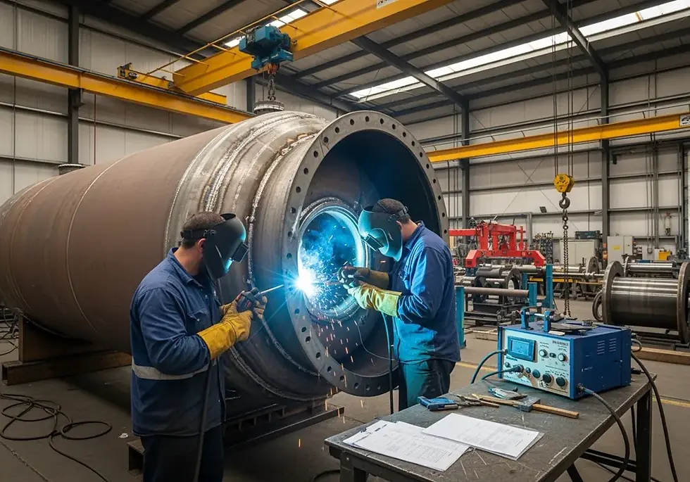
Oil and gas facilities operate under some of the most demanding conditions in industrial processing. Heat exchangers in these environments face extreme temperatures, corrosive process streams, high operating pressures, and continuous service that can exceed 8,000 hours annually. Selecting the wrong materials or design configuration leads to premature failure, unplanned shutdowns, and safety risks - consequences far more costly than the initial equipment saving.
Material selection and thermal design determine whether oil and gas heat exchanger equipment achieves its designed service life or requires early replacement. The decisions made at the specification stage affect performance and reliability for the lifetime of the equipment, not just during the first years of operation.
This guide covers the key material and design considerations for heat exchangers in upstream, midstream, and downstream oil and gas applications, with reference to applicable Australian and international codes.
Operating Conditions in Oil and Gas Applications
Temperature, Pressure, and Corrosion Challenges
Petroleum processing subjects oil gas heat exchanger equipment to conditions that would rapidly destroy equipment designed for standard industrial use. Crude oil contains sulphur compounds, salts, and organic acids that attack metal surfaces at elevated temperatures. Natural gas streams carry hydrogen sulphide and carbon dioxide that cause stress corrosion cracking in susceptible alloys. These are not edge case conditions - they are the normal operating environment for most refinery and gas processing heat exchangers.
Temperature ranges in oil and gas service are broad. Crude distillation units operate at temperatures well above 300°C, whilst cryogenic gas processing reaches temperatures well below zero. Some applications cycle between temperature extremes during startup and shutdown sequences, creating thermal stress demands that add to the corrosion challenge. Pressure ratings in oil and gas service span a wide range, with some applications requiring thick-walled pressure vessels built to ASME Section VIII Division 1 or Division 2. The process cooling design requirements for these applications go well beyond what standard industrial heat exchanger specifications address.
Fouling Characteristics of Petroleum Streams
Fouling accumulates in petroleum service through several mechanisms. Asphaltenes, waxes, and coke-like deposits build up on tube surfaces over time, reducing heat transfer efficiency and increasing pressure drop. This necessitates designs that allow mechanical cleaning or chemical circulation between cleaning intervals.
Tube-side velocity is the primary operational variable for fouling control. Higher velocities reduce the rate of particle deposition and help dislodge soft deposits before they consolidate. However, velocities high enough to cause erosion in two-phase flow or where solids are present must be avoided. The shell and tube heat exchanger fouling management design balance between fouling prevention and erosion risk is a key thermal design decision.
Material Selection for Corrosive Service
Most oil and gas applications require upgraded metallurgy beyond carbon steel. The correct choice depends on the specific corrosive components present in process streams and the operating temperature.
Stainless Steel Options
Austenitic Grades for Moderate Corrosion
Type 304 stainless steel handles mildly corrosive environments but is susceptible to chloride stress corrosion cracking, which limits its use in streams containing chlorides at elevated temperatures. Type 316 stainless steel, with its molybdenum content, provides better resistance to pitting and crevice corrosion in brackish water and some sour gas applications. The heat exchanger material selection oil gas decision between 304 and 316 often hinges on chloride concentration and temperature combination.
Duplex and Super Duplex Grades
Duplex stainless steels combine austenitic and ferritic microstructures, delivering higher strength than 316 stainless with superior chloride stress corrosion cracking resistance. These alloys suit seawater cooling at offshore platforms and other high-chloride environments. Super duplex grades handle the most aggressive chloride conditions, including hot seawater and high-chloride produced water streams.
High-Nickel Alloys
Monel and Inconel for Extreme Service
Sour gas service - streams containing hydrogen sulphide at concentrations that cause sulfide stress cracking in susceptible alloys - may require nickel-based materials. Monel 400 resists sulphuric acid and hydrofluoric acid attack, making it suitable for refinery alkylation unit service. Inconel 625 maintains corrosion resistance at elevated temperatures for high-temperature reformer and fired heater applications.
Hastelloy for Acid Environments
Hastelloy C-276 provides resistance to both oxidising and reducing acid environments, making it suitable for sour water strippers and amine regeneration systems where both hydrogen sulphide and carbon dioxide are present simultaneously. These are among the most aggressive common corrosion environments in gas processing.
Titanium and Exotic Alloys
Titanium offers excellent chloride corrosion resistance at temperatures within its service range. Offshore platforms use titanium tubes in seawater-cooled exchangers because the material's durability in continuous salt water service substantially exceeds that of copper-nickel alloys. Tantalum and zirconium handle the most aggressive acid conditions but cost is high relative to stainless steel - these materials appear only where no other option is viable.
TEMA Class R Design Configuration
TEMA Class R construction defines the most robust shell and tube heat exchanger construction class for refinery and severe industrial service. The process cooling design requirements of TEMA Class R reflect the operating realities of petroleum processing. Heat exchanger material selection oil gas projects must align with the TEMA class R heat exchanger construction requirements because material specification and mechanical design are interdependent - a duplex stainless tube in a carbon steel fixed tubesheet with inadequate joint design provides neither the corrosion resistance nor the structural reliability the service demands.
Construction Requirements
TEMA Class R sets minimum shell thickness regardless of pressure calculation results, full-penetration welds on all pressure-containing joints, and removable tube bundles that allow the bundle to be extracted from the shell for inspection and cleaning without removing the entire exchanger from its piping. Tube sheet thickness minimums are higher than in lighter TEMA classes, and tube-to-tubesheet joints must be grooved and seal-welded to prevent tube pullout under thermal cycling and vibration loads.
Flanges must meet ASME B16.5 or B16.47 standards. Ring-type joint (RTJ) flanges provide superior sealing in high-pressure, high-temperature service and are standard in many refinery applications where raised-face flanges would present a leak risk.
Baffle Design Considerations
Segmental baffles direct shell-side flow across tubes to maximise heat transfer. However, baffle spacing must be controlled within defined limits relative to shell diameter. Spacing that is too close increases pressure drop and can induce flow-induced vibration that damages tubes. TEMA Class R heat exchanger designs specify baffle spacing based on tube diameter, span, and fluid velocity to keep tube natural frequencies safely above the excitation frequency of the flow.
Double-segmental and triple-segmental baffles reduce shell-side pressure drop compared to single-segmental designs by splitting the flow across the bundle. This is beneficial in applications where shell-side pressure drop directly affects pumping costs or where lower-velocity flow reduces fouling tendency. Rod baffles eliminate the stagnant zones behind traditional segmental baffles, reducing fouling in heavy crude and high-viscosity services.
Tube Layout and Pitch Selection
Square pitch tube layout allows mechanical tube cleaning with brushes or high-pressure water lances, making it the standard for crude oil and other fouling services where regular in-service cleaning is planned. Triangular pitch packs more tubes into the same shell diameter for equivalent surface area, but prevents mechanical cleaning and is reserved for clean service or where chemical cleaning is the accepted maintenance method.
Fixed vs Floating Head Designs
Fixed tubesheet exchangers are simpler and less expensive than floating head designs, but cannot accommodate large differential thermal expansion between shell and tube sides. Applications where the temperature difference between the two sides is substantial during operation require floating head configurations. U-tube bundles are the most economical floating head design but cannot be mechanically cleaned on the return bend side. Pull-through floating head designs allow complete tube bundle removal for full inspection and cleaning access.
Thermal Design for Hydrocarbon Processing
Heat transfer calculations for petroleum service differ from clean water applications due to fouling accumulation, viscosity variation with temperature, and phase change in some applications.
Fouling Resistance Factors
TEMA provides fouling resistance factors for various petroleum stream categories. Conservative fouling factor selection prevents the thermal undersizing that results when exchangers are calculated with clean-condition assumptions and then experience rapid performance loss as deposits accumulate. Shell and tube heat exchanger fouling in crude oil service depends on crude quality, flow velocity, and tube surface temperature. Higher tube-side velocities reduce fouling by suppressing particle deposition. The TEMA class R heat exchanger specification addresses fouling by requiring minimum tube velocities and providing fouling factor guidance for common petroleum streams.
For applications where plate heat exchangers are being considered alongside shell and tube units for oil and gas process cooling duties, cooling systems analysis can model both configurations against actual process conditions to identify which provides better thermal efficiency and lifecycle cost for the specific fluid properties and fouling characteristics.
Viscosity Effects on Heat Transfer
Heavy crude oil viscosity varies substantially between ambient and elevated operating temperatures. High viscosity at lower temperatures significantly reduces shell-side heat transfer coefficients compared to lower-viscosity fluids at operating temperature. This viscosity effect means that thermal calculations for crude service must use fluid properties at actual operating temperature, not ambient conditions. Temperature-dependent property variations require iterative calculation methods that account for property changes across the length of the exchanger.
Phase Change Considerations
Condensing hydrocarbon vapours in horizontal exchangers requires vapour entry at the top with condensate drainage from the bottom. Reboilers and partial vaporisers must prevent tube dry-out that causes local overheating and accelerated tube failure. Kettle reboilers provide a liquid reservoir above the tube bundle that maintains tube submergence. Thermosiphon reboilers rely on natural circulation driven by density differences between the liquid feed and the vapour-liquid mixture returning from the bundle.
Pressure Vessel Code Compliance
ASME Section VIII Requirements
Division 1 of ASME Section VIII provides prescriptive design rules suitable for most refinery applications. Division 2 uses design-by-analysis methods with less conservative safety factors, resulting in lighter equipment for high-pressure applications where the additional engineering cost is justified. Both divisions require a quality system audited by an Authorised Inspector and produce documented design calculations and material certifications.
Australian Standard AS1210
AS1210 governs pressure vessel design and construction in Australia. Design verification by a Registered Professional Engineer is required. Fabrication must be carried out by manufacturers accredited by the Australian Institute of Pressure Vessel Inspectors (AICIP). Testing requirements including hydrostatic testing at defined multiples of design pressure apply to all pressure-containing vessels. Pressure vessel inspections by AICIP-accredited inspectors verify ongoing statutory compliance after commissioning.
Inspection and Testing Protocols
Non-Destructive Examination Methods
Radiographic testing examines weld quality in pressure-containing joints and detects subsurface defects. Ultrasonic testing supplements radiography for thick-walled sections where radiographic sensitivity is reduced. Liquid penetrant testing identifies surface-breaking cracks in austenitic stainless steel welds and base metal where magnetic particle testing is not applicable. Magnetic particle testing detects surface and near-surface defects in ferritic and martensitic materials.
Pressure Testing and Material Verification
Hydrostatic testing at above design pressure with defined hold periods verifies pressure integrity before the vessel enters service. Pneumatic testing using compressed gas is reserved for situations where water cannot be used due to process incompatibility or freezing risk, and carries more stringent safety requirements due to the higher stored energy of compressed gas.
Positive material identification (PMI) using handheld XRF analysis verifies that installed materials match the design specification. This is particularly important where multiple alloys are used in the same fabrication, as incorrect alloy substitution in pressure-containing components creates safety risks that may not be apparent until service failure occurs. Mill test reports providing certified chemical composition and mechanical properties for all materials must be maintained for the vessel's service life.
Maintenance and Lifecycle Management
Inspection Intervals and Risk-Based Approaches
API 510 provides risk-based inspection guidance for refinery pressure vessels. Inspection frequency depends on corrosion rate, operating severity, and the consequence of failure for the specific service. Higher-risk services require more frequent inspection intervals. Online monitoring using temperature, pressure, and vibration measurements can provide early warning of developing problems and extend planned inspection intervals by demonstrating that degradation is within acceptable limits between scheduled outages.
Tube Bundle Maintenance
Chemical cleaning dissolves fouling deposits without requiring bundle removal. Circulating cleaning solutions at appropriate temperature removes organic deposits and some scale. Mechanical cleaning requires bundle removal and high-pressure water jetting or tube brushing to remove harder deposits that chemical methods cannot dissolve. Retubing replaces damaged or corroded tubes whilst retaining the shell, heads, and other major components, extending equipment service life at a fraction of complete replacement cost. Repair and maintenance services covering regasketing, retubing, pressure testing, and performance restoration apply to all heat exchanger types in petroleum service.
Custom Engineering for Specific Applications
Crude Preheat Train Design
Crude distillation units use multiple shell and tube heat exchangers in series to recover heat from product streams. Pinch analysis identifies the optimal heat recovery network arrangement to maximise energy recovery. Shell-side fluids flowing counter-current to tube-side crude oil maximise temperature approach and heat recovery. Hydraulic design must ensure proper flow distribution across parallel exchangers in the preheat train.
Sour Water and Amine System Heat Exchangers
Sour water strippers process water contaminated with hydrogen sulphide and ammonia. Heat exchangers in this service face both corrosion and fouling from iron sulphide and ammonium salt deposits. Removable tube bundles are standard for this service to allow periodic cleaning without vessel removal.
Amine solutions used for gas sweetening are corrosive to carbon steel at elevated temperatures, particularly when carbon dioxide and hydrogen sulphide are present. Stainless steel tubes prevent corrosion whilst carbon steel shells with corrosion allowance reduce overall cost. Amine foaming in exchangers can cause operational problems if shell-side velocity is not controlled within appropriate limits, and impingement plates protect tube bundles from inlet flow momentum.
Allied Heat Transfer manufactures and supplies custom heat exchangers for oil and gas processing applications, with over 25 years of thermal engineering experience across upstream, midstream, and downstream Australian facilities.
Conclusion
Material selection and thermal design determine oil and gas heat exchanger reliability and service life. Carbon steel suits only the mildest services - most applications require stainless steel, duplex alloys, or high-nickel materials to resist corrosion from sulphur compounds, acids, and chlorides. TEMA Class R construction provides the robust mechanical design necessary for refinery service. Thermal calculations for oil gas heat exchanger duty must account for fouling, viscosity, and phase change characteristics that distinguish petroleum service from clean fluid applications. The process cooling design framework presented here - from material selection through to maintenance strategy - applies across upstream, midstream, and downstream Australian facilities.
Compliance with ASME Section VIII or AS1210 ensures pressure vessel integrity. Proactive maintenance through planned inspection, cleaning, and timely retubing extends equipment service life substantially compared to reactive intervention. For technical consultation on heat exchanger specifications for an oil and gas project, reach out to our industrial heat transfer team to discuss material options and design requirements.


